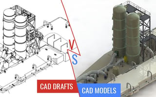
Fabricators deal with the process of assembling components almost on daily basis, and at times series of assembly operations all throughout their day. Fabricators fabricating anything from a small sheet metal furniture piece to car chassis need assembly drawings or models to perform uninterrupted fabrication and avoid running to design engineer in between ongoing operation.
A CAD design engineer will be able to provide any of them and it lies in his capabilities to generate both. It is fabricators’ decision as to which one should he adopt is the concern. It’s been a legacy of having a mindset that a fabricator needs drawing and models are for designing and design intent communication. These words, drawings and models lead us to think which is better. Since drawings have a traditional association with fabrication, we really need to rethink the fact if models can replace their functioning.
Base your choice weighing all factors
1. Product based
But we often forget that 2D CAD drawings are difficult to interpret unless they are for simpler products such as furniture or architectural ornamental products. Soon as the product design complicates, to a level of a machine element or chassis – basically has more than one part – 2D CAD drafts starts showing their limitation.
Although an assembly drawing is populated with balloons, 2D drafts are always misleading in case of complex and multi-component assembly. This challenge is eliminated with 3D geometry annotated with PMI. As all the information pertaining to fabrication is annotated in 3D model, GD&T is specified clearly, foreman on the shop floor doesn’t have to run to designer asking questions about every detail and symbol. Any typical CAD platform such as SolidWorks or Autodesk’s Inventor will generate such a comprehensive model very efficiently.
2. Intended use
Now moving slightly away from the typical fabrication shop floor, let us concentrate on the Bill of Materials generation for actual fabrication. Purchasing division uses technical packages of drawings for generating any purchasing needs. Also, marketing division has a significant usage of 2D drafts for developing publications.
However, these drawings are affecting productivity and fail to establish a seamless communication when it comes to cross-disciplinary communication. Also with the advent of Industry 4.0 these drawings are becoming obsolete and fail to connect with external enterprise as finely as models can.
3. Thinking beyond designs
Testing designs and validating it virtually in a model environment is the way to reduce errors, time for design development and reducing costs. It isn’t possible for to carry out physical tests, validate limiting values of pressure, temperature, stresses, forces or any other physical phenomenon with 2D drafts. A 3D CAD model serves as the prototype of the actual model to validate the design geometry and topography for the intended use.
4. Enhancing profitability
When fabricators are able to differentiate a sheet metal part from a plastic component, they can essentially sell it better to the retailers. Rendering gives these characteristics and physical attributes to the CAD models. This is beyond imagination in 2D draft, except for labeling it or mentioning the properties with annotations.
Also, Conversion of 2D to 3D Sheet metal design in SolidWorks will enable you to treat a certain 3D CAD solid model as sheet metal component and not any other CAD part. This means, there will be consideration of DFM guidelines while modeling and eliminates errors.
5. Considering the client’s mindset
Now when it comes to explaining design intent, there are certain details that are missing in 2D assembly drawings. For example, hidden lines are completely eliminated from assembly drawings, failing to explain the exact geometry. Also, the dimensions that are needed to assemble the parts are shown in the drawings and need separate detailed drawings to specify dimensions and manufacturing notes.
On the other hand model in SolidWorks will eliminate all these and enable giving a comprehensive view of the component. An exploded assembly model will also show how each part fit with each other and reveal how each part fit with each other which otherwise would be hidden.
While one may argue that all these can be done in assembly drawings as well, but when put in 3D it is self-explanatory.
6. Designer’s perspective
What a CAD product design engineer does is link a group of solid parts, joins them in alignment and prepares a single assembly model. This virtual joining allows the designer to examine the interface of parts, limits, fits and tolerances for mating parts – such as a shaft in a hole.
Owing to these, designer naturally needs to have a control and see vivid details from different perspective – feature that is clearly absent with 2D drafts. Being able to specify the material of the part being designed automatically develops insights and hence the better outcome.
To sum it all up, although we have always a concept of drawings when it comes to fabrication we got to accept the fact that 3D models do the exact job in a better manner. Especially when it is the case of multi-component assembly, it becomes inevitable to have a model of the part to be manufactured.


